Installing a Jet Kit
Original article printed Sport Rider, August 1997
(With
Factory Pro Notes added August 19, 2000)
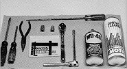
Tools needed for the job include:
Assorted length and size Phillips and
flat-blade screwdrivers ( the long screwdriver may be needed for on-bike adjustment of the
idle fuel screw; a long Phillips screwdriver or hex-wrench socket with extension may be
needed to reach the manifold clamps); needle nose pliers; assorted ratchets, sockets and
extensions (for removal of fuel tank); a float-level measurement tool or small ruler
graded in millimeters (optional); and a can of WD-40 and contact cleaner. Tools not
pictured are an open end 8mm wrench (for tightening/holding the emulsion tube when
changing main jets), a 6mm socket and ratchet and a shop manual. Dialing in the
carburetion will take time, so be patient. Most of the jet-kit manufacturers have tech
lines to help you with carburetor tuning. |
 |
Factory
Pro's US / Canada Toll free Tech Support
1 (800) 869-0497
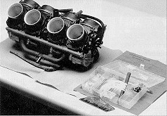 |
Installing a performance
exhaust system is one of the first modifications people make to their sport bikes. But in
order to reap the full benefits of the increased flow (and usually to ensure the engine
even runs properly), an aftermarket carburetor jet kit is required. Improved flow at the
exhaust side usually results in an engine flowing more air on the intake side, meaning
that the carburetors must compensate with more fuel to ensure the correct mixture.
Although a carburetor seems incredibly complicated, its inner workings are fairly
straightforward, and as long as you take each step in a jet kit installation carefully,
you'll be well on your way to improved performance |
Factory
Pro's Kits are the choice of most of the AMA privateer teams. Factory Pro
provides full 4 Gas EC997 Eddy Current Dynamometer Tuning Service for AMA
competitors. The EC997 Dyno is THE primary choice of most teams at AMA.
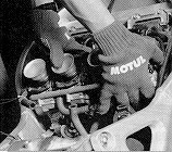
| Removal of the fuel tank is usually your first task.
Before removing anything, find the location of the fuel petcock and the main fuel line
from the intake manifolds activating the petcock, yet some of these still have an
"off" position. Some also require tilting the fuel-tank attachment bolts, tilt
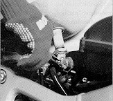
the tank up and use needle-nose pliers to loosen the fuel-line hose clamp. After removing
the fuel line, use this trick: Set the fuel tank in an old tire, so that it remains level
and avoids damage to the petcock. If it's laid on the ground at an angle, fuel may leak
out of the overflow vent. Keep track of all the vent hoses leading to the gas tank (write
it in a notepad, or label them with masking tape), so you can correctly reinstall them
afterwards. |
 |
 |
.
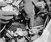
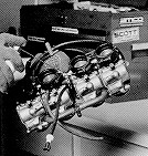
| After removing the airbox (being careful to document all
hoses leading to and from the airbox), loosen the carburetor manifold clamps. Most take
Phillips screwdriver, but some require a hex-key extension for this job. With all manifold
clamps loosened, grasp the carbs firmly and remove them, using a "rocking"
motion to free the manifolds. Be firm, but don't get too rough. Drain the fuel from the
carbs into a container using the drain screw on the bottom of the float bowls. |
 |
 |
Before removing the throttle cables, check
that nothing has fallen inside the the intake manifolds, and seal them with rag or tape. Do
not skip this step. We don't need to tell you what will happen if a bolt or other
object falls inside the intake port unnoticed. Removing the throttle cables from the carbs
may take a little practice; because of the push/pull actuation, you'll need to turn the
linkage with your fingers to free up the cable ends for removal. |
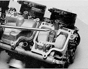
| Invert the carbs, and remove the float bowls carefully.
The main jet (indicated by the screwdriver), which controls fuel flow from the midrange to
top-end, is the first component to be changed. Using a flat-blade screwdriver, carefully
remove the main jet, taking care not to damage the floats on either side. In fact, try to
avoid touching the floats, since you may accidentally bend the float tang, altering float
height (next step). When removing the main jet, you may need an 8mm open-end wrench to
hold the emulsion tube (which the main jet screws into). Check the jet kit's instructions
for replacement size recommendations. Check the condition of the float-bowl gasket, and
remove any dirt before reinstalling. |
 |
|

|
The majority of (Honda)
jet kits don't require you to adjust the
float height; call the manufacturer ahead of time to see if your application may require
this adjustment. If so, you'll need a height measurement tool like the one pictured
(available from most Honda dealers or direct from Factory Pro), a pair of
vernier or digital calipers or a small ruler with millimeter markings. Make
sure
the bottom edge of the float bowl is level, and carefully measure the distance from the
edge of the float. Don't be a hamfist here; the float mechanism is very delicate.
Adjustments are made by carefully bending the float tang (located at the float's pivot
point),. either by gently pushing downward the float, or bending the tang manually.
Note! The pic shows the carbs UP SIDE DOWN! They should only be tilted! The
float valve spring should NOT be compressed! |
(Factory
Pro Notes:
It is extremely important that you DO NOT compress the float valve
spring loaded plunger when measuring, except on the 95-97 ZX6r, where you DO
compress and bottom out the float valve spring.
Note: Even though the above picture shows the carbs totally inverted - with all
the weight of the floats compressing the float valve spring, we all know that
the carbs should be only "tilted" so that the float "tang"
touches and closes the float valve, but does not compress the float valve spring
on the little plunger! that is in the float valve!
Marc)
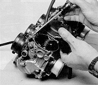
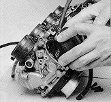
| Most jet kits require changing the needles and
slide springs, which control lower-to-upper midrange carburetion. When removing the carb
diaphragm covers, some carbs have a small O-ring on the diaphragm's edge (indicated by the
screwdriver). Take care not to loose these, otherwise the slide will not work properly. Be
careful not to damage the diaphragm/slide assembly/jet needle during removal. Note the
fitment of the slide spring on the diaphragm cover. Incorrect installation of the
accessory spring will cause slide malfunction, as well. Clean off any dirt in the
diaphragm seal groove. |
 |
(Factory
Pro Notes: If the original needle had a thin steel or brass shim washer below
the needle clip or spacer, unless the Carb Recal Kit specifically states to
remove it, you will use the thin metal spacer with the Factory Pro needle. If
the original needle has a 2.5mm / .100" plastic spacer under the clip, you
will ALWAYS use that with our needle!)
 |
When replacing the needle (protruding from beneath the
slide), handle the slide assembly carefully to avoid damaging the diaphragm. The needle is
usually held in place with a plug of some sort; check your jet kit instructions for proper
removal procedure. When removing the needle, note that there may be a tiny washer that
sits underneath the top of the needle. Keep the washer, as you may be needing it later
when dialing in the needle position for midrange tuning. |
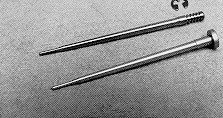
| The main advantage of a jet kit is the ability to alter
the needle "height" to dial in carburetion for various applications. Note that
the aftermarket needle (top) has a circlip, which can be set in any of the grooves in the
top portion of the needle, while the stock needle (bottom) has no adjustment. Check your
jet-kit instructions for proper "base" clip setting. Note that the positions are
counted from the top of the needle down: The "number three position" is the
third groove from the top. The easiest method for installation/removal of the circlip is
to place it in the desired groove, and gently force it in, by pressing the needle and clip
against a flat surface. Place the open end of the circlip against a flat surface to
remove. Be careful while handling the needles, as they are precision-machined pieces;
bending them even the slightest amount renders them useless. |
 |
Factory
Pro Notes:
A better description of a jet kit is a supply the parts necessary to properly
tune a particular make / model / with the listed mods (like exhaust system, air
filter, etc.).
Is the needle the most important part of the kit? Very important, but not really
the only item that reduces power output. R&D time is distributed throughout
the entire package, like main jet stagger, pilot jet size, float height / fuel
level settings, emulsion tube design and additional tuning information. The
needle is very important, but often, more work is involved in the other items
that must be changed to develop an assembly of parts that will produce a desired
fuel curve that, with the correct main jet, will produce best power.|
How much time for each component and the total kit R&D? It's a judgment call
and is the result of the accuracy of your test equipment and the designer's curiosity,
creativity and stubbornness. We've spent as much as 6 weeks, as on the 95-97
ZX6r (virtually EVERY Kawasaki race team ended up with that kit in the US) and 5
months to properly design and manufacture the kit that eliminated the on/off
throttle problem for the 2000 model ZX9r's. We ARE stubborn.
Why does the other carb kit manufacturer sell a cheaper kit that does nothing
but aggravate the on/off throttle problem? Not because the don't want to fix it,
but that their best dynos (high inertia dynos with an eddy current brake stuck
on the end of a 900# drum) simply aren't able to quantify or even see the
problem!
 |
After setting the clip to the desired groove ( the washer
that you saved from the stock needle setup can be used for half-step increments between
grooves), carefully reinstall the needle, making sure the needle holder is correctly set
in the slide. When reinstalling the slide assembly, ensure the needle fits into the
emulsion tube as the slide moves into place. The diaphragm's edge must fit into the groove
atop the chamber. Don't forget the O-ring (step 8) if needed. Fit the
accessory spring (
if supplied in the kit), and carefully install the cover, making sure that the diaphragm's edge is
"slotted" correctly. |
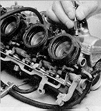
| The final modification is to adjust the idle fuel screw. On
this particular setup, the screw is accessible with a special tool included in the kit. On
some older carbs, however, the screw is covered with an aluminum plug, which requires a
drill to remove. Check your kit instructions for the correct procedure. |
|
Factory
Pro Notes:
On US Honda's, the fuel screw is usually adjusted with a "D"
wrench and it is not covered by a cap.
On some older style Keihin carbs, as on the NT650, the fuel screws are
located just below the throttle shaft pulley, covered by an aluminum cap and are
adjusted with a flat bladed screwdriver.
On Kawasaki Keihin carbs, the fuel screw is in the same location as the
cbr900 carbs shown above, covered by an aluminum cap and are adjusted with a
flat bladed screwdriver.
On modern Mikuni carbs, the fuel screw is also located in the same place,
covered by an aluminum cap and are adjusted with a flat bladed screwdriver.
|

|
When reinstalling the carb assembly, spraying WD-40 or other
light lubricant onto the manifolds eases reassembly. Of course, make sure to remove the
intake port covers before installation. Hooking up the throttle cables may take a little
practice: you'll probably need needle-nose pliers to insert the cable end into the
throttle linkage drum. Ensure that the manifolds are correctly installed on the intake
port spigots (or that the carbs are fully inserted into the rubber manifolds, if removed
in that manner), and tighten the manifold clamps. After reinstalling all components, check
that the throttle works correctly without binding when moving the bars lock-to-lock. |
Factory Pro
Tuning
1 (415) 883-5620


