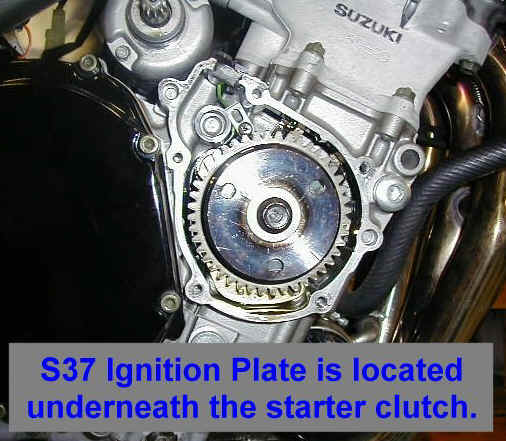
A look in. Location of ignition trigger mounting plate on: gsxr600, 97-01 (and similar) 1. Remove the outer "palm sized" small starter cover (already removed). 2. Remove the inner, larger starter clutch cover (already removed). Remember, there is a screw in the upper left of the inner cover that is not accessible until the small, outer cover is removed. You will probably reuse the gasket 3. Remove the starter clutch bolt with a 14mm air wrench (that's the easiest and quickest way). 4. Remove the original ignition plate from the engine cases with a #2 Phillips screwdriver. (it's under the starter clutch gear)
|
|
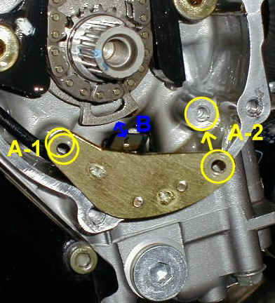
| 5. With a flatbladed screwdriver, remove the ignition trigger
coil from the original mounting plate and reinstall it onto the new Factory
Pro ignition plate. Be careful NOT to stab yourself with the screwdriver! Note: The gold
center core plate (at B, down arrow) of the
coil assembly MUST extent "proud" of the surrounding off-white
epoxy area when
installed and tightened. There is a small amount of play to adjust with, and it must
project outwards, towards the ignition rotor, usually ~.005" to .010".
(In other words, a real little bit) 6. After installing the trigger coil to the ignition plate, temporarily reinstall the starter clutch and bolt and rotate the engine so that rotor projection at B, up arrow is aligned with the trigger coil (so you can measure the trigger coil clearance). 7. Install A-1phillips screw, snug. Install A-2 Phillips screw and snug down. 8. Measure the clearance at B. It should be
.015" to .020". Adjust by loosening A-1 and A-2 and pushing the plate towards the
rotor. Tighten screws when done. 2. So - you cracked the magnet because
you didn't line up the locating hole......
|
|
| 9. Check the tightness of the coil plate screws,
reinstall the ignition plate. Use a bit of light strength thread locking compound on the
screws if you want, for a good job. 10. Reinstall the starter clutch and mounting bolt. BE SURE to line up the indexing marks on the crankshaft end and the starter clutch or the TDC marks will be wrong and that could cause big problems if using the TDC marks to adjust the valves later..... 11. Reinstall the covers (don't forget the screw under the small cover). Replace or reseal gaskets as necessary. 12. You should not have any parts left over, except for the old ignition plate. |
|